- cheap
- lightweight
- not for high keying speeds
- using scrap parts from my junkbox
- keying up to 16 WPM, perhaps more
- total cost of 2 EURO
- total build time of 2 hours
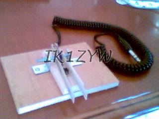
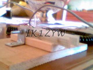
Figure 1: the whole key
Once I have built a PIC16F84 based IAMBIC keyer, and also bought an IC706MKIIG that includes that feature, I needed the KEY! :-)
Given the price of a brand new horizontal key, I decided to build one.
Sorry for the bad quality pictures! They were taken with a simple webcam.
Requirements:
|
Figure 1: the whole key |
I will tend to give guidelines how to build your key, since I doubt you can get hold of my very same parts. I do not sell keys (well, with enough money you can convince me :-)), I rather prefer to encourage you to build your own.
Key base
Wood! It's cheap and very easy to cut, nail, glue, ... I needed two pieces. The base is some 10x10 cm, 1 cm thick. The second is 8x3 cm (from a 250x3x1 cm stick), 1 cm thick.
The second piece is glued in the centre of the bigger base using cyano-acrylic glue (like the one from "Locktite", known as "Attack" in Italy).
Electric part
On the website of a Japanese HAM I have seen pictures of a IAMBIC key that uses two normally-open push-buttons for keying. Neat idea!
At the nearest electronic shop I selected two identical miniature push-buttons that can be glued back-to-back. The two switches must implement the keying electric contact on the same (horizontal) axis. (But the final key can tolerate a slight disalignment, then adjusted with asymmetrical paddle setup.) Therefore their pins must allow to be bent in such a way that they don't touch eachother.
There are several types of buttons. Those I got generate an audible "click" whenever they are pressed. They are used in keyboards and general purpose electronic devices. They need some pressure from your fingers through the paddles, that's the reason for the limited maximum speed. I can't say how many clicks they can handle...
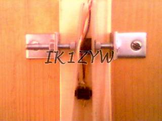
You will glue the buttons back-to-back, and then glue them to the wodden base, in the middle of paddles length. Refer to Figures 2 and 3 for a visual aid. IMPORTANT: first solder the electric cord to the buttons (see below), THEN glue them to the base!
Paddles
These should not be flexible: they have to transfer your pressure to the push-button, rather than bend. Due to lack of material at home, I took two pieces of a "breadboard" (perhaps called "paddy board" somewhere else; used to build prototypes of electronic circuits), cut at 8x1.5 cm. I think any copper-plated vetronite board would do as well. 8 centimetres of this material allow a precise keying.
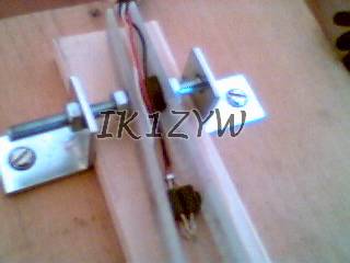
Now the problem is: how do I keep these things vertical while my key base is horizontal?! Please refer to Figures 2 and 3 to understand what follows.
My solution requires two L-shaped metallic plates (bought at the hardware store, but you can make your own if you have the equipment!) with one hole per L-leg. Get a bolt (with 3 nuts) that can pass through the holes. Then drill a hole on each paddle-to-be at about 2 cm from one end. Add a cylindrical hard-rubber spacer whose length is some millimetres less than the distance between the two pressure points on the push-buttons and.... you have everything.
Now you need to nail the L-plates on the key base, at an appropriate distance. Because of the height of the holes, I added a 1cm thick support underneath the push-buttons and the paddles (see Figure 4). You can use wider paddles instead (I had already cut mine).
Now pass the bolt through the first hole. Holding its tip in between the two holes of the L-plates, insert, in this order: a nut, a paddle, the rubber spacer, the second paddle, the second nut. Now pass the tip of the bolt through the second hole, and block it using the third nut.
You need no mean of pulling the paddles backwards into rest position, since the push-button itself generates enough strength to repell the paddle once you release the finger pressure.
Key cord
For connecting the key to the keyer/RTX you need a 3 wire cord. I used one recovered from a broken pair of stereo headphones. Prepare the push-buttons as follows. Match and solder together one pin per button. You will then have two pins together, and two free (one per button). It is like connecting in series the two switches.
Solder the "common" wire of the cord to the two pins together (the center of the series), and the two remaining wires to the two free pins.
Remember: the connector tip goes to the left paddle, the connector middle is for the right paddle, and the common wire for the third contact.
Conclusions
Considering that I have NEVER felt a commercial IAMBIC key, my 0.1beta version seems to work reasonably well. There are limitations on the speed, but for a newbie, whose operating speed is certainly limited, the performance/price ratio is outstanding.
Another positive factor is that you can have no fear to go field-day with such a basic key: quick fixes in case of troubles are possible, and who cares if it falls into water, down a cliff, ...?!
Because of the finger pressure needed for keying, the base must be stabilized with four rubber feet. Or make it somehow heavier.
I am already thinking of improvements, such as using a different pair of switches. The shop attendant showed me a push-button that has a longer button "run", but does not "click". I would be able to add a mechanical control of the paddle sensitivity (how much you have to move it before there is electric contact), therefore would probably allow faster keying.
I have no idea what is the MTBF (Mean Time Between Failures) for these switches, in other words, how long they will last. They might break during a QSO (when, else? :-)). I shall not be liable for any DX lost!
See you in CW!
(c) Paolo Cravero, 16-Dec-2001. ik1zyw at yahoo! dot com

Eccetto dove diversamente specificato, i contenuti di questo sito sono rilasciati sotto Licenza Creative Commons.
The material on this page is licensed under a Creative Commons License, unless otherwise noted.