Ever lost your Internet connection because someone picked up the other phone of your house? If the answer is yes, then you probably need a visual phone line monitor!
WARNING! This circuit might draw too much current from the phoneline, causing it to hang when receiving a call! Building half of it, just the green LED side, cured the problem. (added 8-Feb-2003)
What I introduce here is not my own creation, but rather an adaptation of a circuit I found on the Net [1]. The adaptation was needed because I used only parts that I had at home.
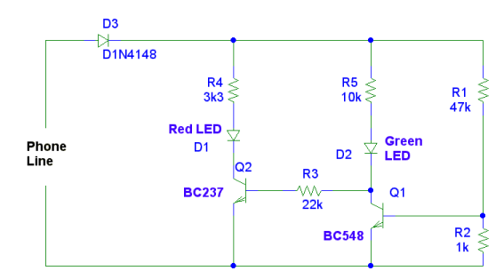
Schematic
Installation
Phone line voltages are not risky for human beings, still, don't play around with your wet hands: you are on your own, whatever you decide to do with this circuit. That's for the disclaimer part.
The phone line carries contiuously a DC voltage, plus the conversation or a 25 Hz AC when ringing. You need a tester to find out the correct polarity of your plug, so that the line monitor gets polarized correctly. The original design showed a rectifying bridge, but I believe it is just an extra cost.
Connect line's + terminal to D3, and the other to the "ground" of the line monitor.
Comments
The circuit is self-explainatory. I admit I haven't gone into calculations of transistor polarization. I put together the components on the prototyping breadboard and fired it up.
The (Italian) phone line provides 40 to 60 V DC in rest position, and 8
to 9 V DC during a conversation. Therefore the rightmost transistor Q1 is
in saturation when the circuit is supplied with the high voltage,
whilst it goes OFF when the line is in use.
With 9V supply Q2 is then saturated so that the red LED enlightens.
If you use different transistors you have to play a bit with R2, R4 and R5 to get the correct Q1 polarization and desired LED brightness.
The green LED is always ON, so it works also as a simple night light. Not counting that the phone line is usually powered when the main AC supply goes off for any reason! Uhm, this gives me another idea... 40 Volts, 2 Volts per LED... I can put 20 LEDs in series and get a nice emergency "light" out of the phone line!! Cool, gotta try it! :-)
Improvements
Are there any?! This is such a straightforward circuit that is hard to improve. I have two complementary ideas, though:
Use the red LED only, in order to reduce light pollution of the environment :-) and probably the overall current consumption
Use the green LED only, to indicate that the line is free, in order to simplify the circuit
I have reasons to believe that the latter idea would allow fitting the circuit into a phone plug (the terminator of your phone cable). I'll give it a try: I am afraid the cleaning lady is not so gentle with exposed electronics around the house, so this might be the solution...
Considering what I wrote above about the emergency lamp, do I really need the transistor? I'm thinking of
----|>|---/\/\/\/\----|LED>----
that in ASCII represents a series of diode, resistor and LED. Assuming a voltage drop over the LED and the diode of 2.7 V, 40V of supply and 15mA of current, R = (40-2.7)/0.015 = ca 2500 ohm.
When the voltage drops to 9V, there are only (9-0.7)/2500 = ca 3.3 mA through the LED, so it should be almost off. I think that after playing with resistor value one can get a very simple "line free" monitor. And this one fits into the plug indeed!
Eccetto dove diversamente specificato, i contenuti di questo sito sono rilasciati sotto Licenza Creative Commons.
The material on this page is licensed under a Creative Commons License, unless otherwise noted.