 Menu
Menu
|
Function To show the transformation of mechanical energy into electric energy and its use as a voltage generator. |

| ||
|
|||
|
Description It is a small generator with hand motion. While it presents the example of the transformation of mechanical energy into electric energy, it can also be used for different school experiments: electrolysis and its applications; lighting and heating; transformation of electric energy into mechanical energy; charge of accumulators. It can supply 1 ampere with 25 volts. | |||
 Menu
Menu
|
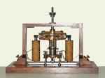
Function Accurate reproduction in all its particulars of Pacinotti’s historical machine. |

| ||
|
|||
|
Description If it is used as a generator in parallel it supplies a current that can be enhanced with a galvanometer. By exciting separately the two inductors we obtain a current to operate a bell. As a engine it can work in series or in parallel. | |||
|
Function To show the functioning of the apparatus and therefore the various systems of alternators. |

| ||
|
|||
|
Description On an iron ring twelve equal windings are winded in five layers of a 3-tenth wire and they can be connected between them in three different manners, by two interruption hooks and four plugs fixed on the basis. According to the directions attached to the apparatus in the first connection (single-phase), the twelve windings are in series and the current is taken on two diametrically opposed points. In the second connection (two-phase), the twelve windings form four sections of three series elements; then the four sections are connected in series: the first with the third and the second with the fourth. In this way we obtain two couples of free ends that will give us the two-phase system. In the third connection, the twelve windings are still connected in series, and the current is taken from three points at 120 degrees one from the other (three-phase system with a delta-connection). The ring is fixed vertically on a brass basis that supports also the inductor system formed by an electromagnet turning in the plane of the ring and stimulated with a battery of accumulators (8 V) or by a direct current with a maximum intensity of 5 A. A heavy flywheel helps to make the electromagnet rotation regular. The connection is all-visible and the ends of the twelve sections are fixed to metallic gaskets, joined between them with mobile bridges, so that we can make different combinations from the one indicated above. | |||
|
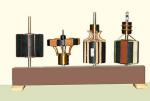
Function To show different types of electric engine rotors. |

| ||
|
|||
|
Description Squirrel-cage for an asynchronous engine. The pack of circular iron plates is a big wooden varnished and grooved core. The two copper conductors, welded to two frontal copper rings are very visible in their holes. Paninotti’s ring. The magnetic core is a 12 cm diameter wooden ring. Six sections of rubberised thread are wounded on the ring and they form a close circuit. The ends of two neighbouring sections are joined to the corresponding collector plate. A drum armature with a two poles winding and a six segment collector. The construction is analogue to the previous one. The windings, that in reality should be superimposed, here are disposed one next to the other in the same hole. Model of a three phase asynchronous engine. It is analogue to the drum one. The winding has three differently coloured sections, that are tidily connected with the starting rings at one end and star connected at the other end. | |||
|
Function Group of two models illustrating polyphase motors. |

| ||
|
|||
|
Description The two models are coupled on the same basis but can be removed from it. Each engine can take a horizontal or vertical position. In the first four-section engine we have the connection of the two-phase alternator; in the second there is an example of the three-phase star connection. The three differently coloured sections have a common start (star centre) represented by a peripheral black conductor, so that in the alternator we have the delta connection and in the engine the star connection. The accessories are: a magnetic needle turning on its axis, an iron cross, an iron disk and a model of rotor. To enhance the existence of the field, we place the engine horizontally after eliminating the mobile vertical support of the engines. We place the glass disk included with the apparatus on it and we cover it with iron shaping (included in a case with a net cover). When we start the motor, we observe that the iron shaping follows the rotating field. If we give the alternator a small acceleration (low frequency) we can observe, in the two-phase engine, observe that the magnetic needle points to the direction of the two fields successively and jerkily. So does the cross that oscillates without a rotating motion except when we start it by hand. Instead the disk and the rotor start rotating whatever the frequency, and they change direction when the direction of the alternator rotation changes or if we change one of the connection wires in the three-phase engine. | |||