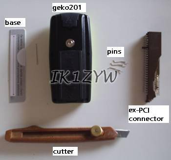
Part of the tools needed...
First of all I measured with a sliding gauge what my Geko 201 expects as a connector: it is something 17 mm wide and as thick as a creditcard. Electric connections are 2.9 mm apart and the slidethrough guide is 0.75 mm wide. If you look at the back of your Geko, you understand what I mean.
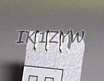
Next step was finding appropriate metallic connectors. After a few thoughts and reading through some web pages, I opted for a dismantled PCI female connector (usually sits on the motherboard). When torn apart, the connector provides a lot of thin metallic strips that can be bent 180° once.
Once I got hold of a volunteer card (that turned out to be a Croatian phonecard), the production could start. Tools needed:
Using ruler and cutter get hold of a 17mm wide strip of the card. I suggest cutting the full length of the card. Try sliding it gently into the back of Geko, until it meets the slidethrough guide. Refine card strip (referred to as "base" from now) dimensions as needed.
With the base in partial place into the Geko, mark on it the center of connectors and the position of slidethrough guide.
Handling carefully the cutter start digging out the slit. Soon the base will slide all the way into Geko.
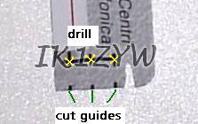
Again with the cutter dig small guides for your electric connectors at the end of the base. Use previously drawn marks to get the position. Then, slightly behind the position of connectors on the Geko, drill a small hole with a needle. Electric connectors, or just a part of them, should pass through the hole when pushed.
Bend the strip as shown in the picture and prepare your serial cable.
When soldering cable wires on the base make sure both ends of connector strips are soldered together.
Part of the tools needed...
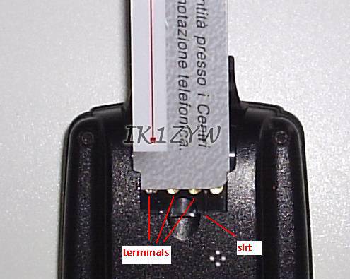
Test insertion. Take measurements of slit and connection points.
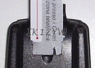
Slit done, the base slides all the way into geko.
A permanent marker will help taking measurements...
WARNING: in the picture "X" signs are AT connector positions. Drill 3-4mm behind them.


Left: slit and holes drilled, light passes through.
Right: connector guides added (sorry for unfocused pic!)
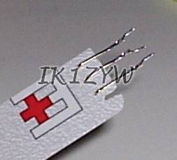
Insert strips into holes and gently straighten free ends with pliers
Bend strips through the pre-cut guides.
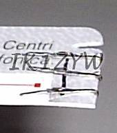
With the help of pliers flatten strips so that through-the-hole ends and
free-ends can be soldered together (visible near the black line).

Eccetto dove diversamente specificato, i contenuti di questo sito sono rilasciati sotto Licenza Creative Commons.
The material on this page is licensed under a Creative Commons License, unless otherwise noted.
Notice: Garmin and geko Trademarks of Garmin Corporation, and there may be references to other trademarks of others - which I respect!