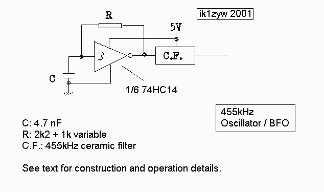
Note 1: you need a bit of knowledge on how a supereterodyna
receiver
works to understand the idea underneath this project.
You also need a 455kHz ceramic filter to build it
Note 2: depending on ceramic filter's bandwidth, this project
should
work with all receivers with an IF between 450 and 460 kHz,
just substitute your IF value to all 455s below.
What I needed was a way to demodulate SSB and CW with those AM only HF commercial receivers. The solution is to insert a BFO before the last IF stage of the receiver (that is usually working at 455kHz). You can find several good projects on Internet. But I did not want to touch the receiver circuits, since it was not mine... Then I read an article about inserting the 455kHz carrier in a less polite way [1] :-) : just put a 455kHz oscillator close to the last IF stage of the receiver, and for simple RF coupling you achieve the same result. That's the way I followed.
The solution proposed in [1] needs a 455kHz IF coil (color red) to work. I wasn't able to find any in my neighborhoud or scrap-box.

The idea underneath is the following. Through the filter I can get a 455kHz sine wave in output, whatever I throw into the filter. Therefore I can generate a square wave at a lower frequency and take only one of its harmonics. I chose to have the oscillator work at one-fifth of 455kHz, so around 91kHz. In order to have more flexibility I made the oscillator work from some 70 to some 130 kHz using a 1kohm variable resistor in series with a 2.2kohm on the feedback line of the inverter. Oscillator's base frequency can be obtained with:
So it is a simple, mono-frequency, frequency multiplier.
Some facts:
Unless you can use a frequency counter, connect a wire (at least 10cm) to the filter output and put it close to a HAM receiver tuned on 455kHz, USB or LSB.
It is also wise to use an indoor antenna or whatever piece of wire that can be put close to our BFO.
Start turning slowly the 1kohm variable resistor until you hear the typical carrier whistle on the receiver. There you are close to 455kHz.
Tune the oscillator until the beat disappears as it is a too low-frequency note to be heard by a human hear (so you have to go from a high-pitched tone to a lower one, until nothing is heard).
Switch to the other SSB mode and make sure nothing can be heard. You are on the right frequency when:
Without a HAM receiver tuning is more difficult. As soon as I experience it, I'll write something here.
Some notes on the receiver. I could get hold of two of them with analog tuning (no PLL). The first, more recent from Sonoko, doesn't use an IF at 455kHz but at 465kHz, therefore this circuit is unuseful. The second RX, older with sensitivity problems, allowed me to decode SSB transmissions. But, althought the BFO frequency was VERY stable (monitoring with the HAM HF receiver), RX's VFO turned out to be rather unstable, thus forcing to continuous tuning corrections or, once stabilized, to listen to a chirped voice. This might be due to a non-stabilized power supply to the receiver (I was using a cheap multi-connector multi-voltage transformer), since I ran out of batteries (PS: this proved to be wrong since the problem persists even with battery powering the receiver, so the receiver is instable).
See my operating notes for some help.
[1] Radio Rivista 10/2000 (ISSN 0033-8036), pp 26-27, by IK1ICD A.Gariano