Right after using with success an homemade reproduction of DK7ZB's VHF 4 element short yagi, I felt the need to make slight changes to accomodate my needs.
My first version used a 10mm square aluminium mast, with 3mm dia holes to hold elements and homebrew spacers using pieces of rubber water pipe. Altought that setup was light enough to be carried around the Alps, I did not feel comfortable with small screws and nuts hanging around the backpack and the operating field. So I wanted to try an all-PVC version of the same antenna.
REMEMBER, I use this antenna occasionally /P on the mountains, the suggested modifications are NOT intended for a permanent installation.
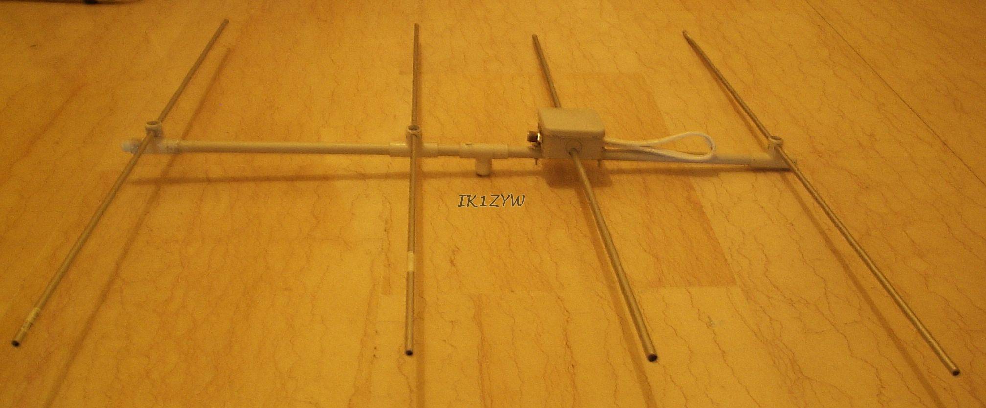
The result is an almost "plug and play" antenna that fits in the backpack and needs no screwdriver/pliers to be assembled.
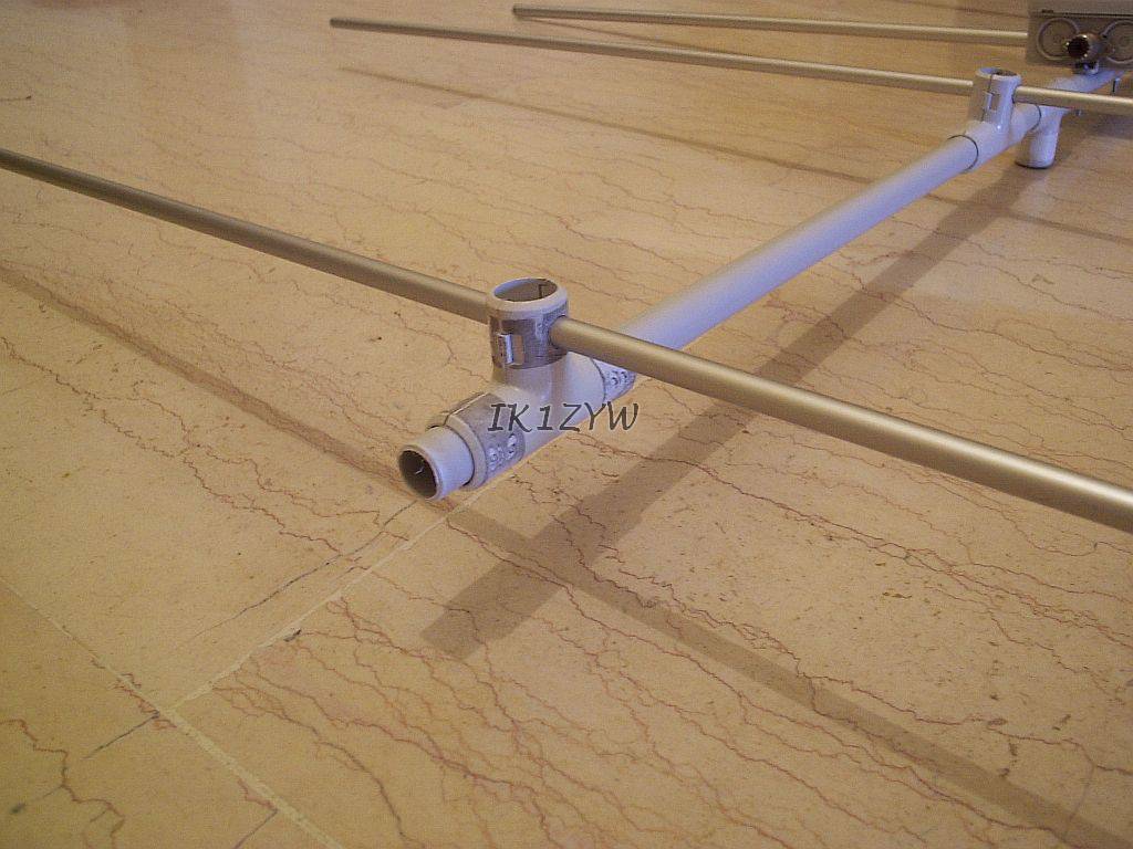
The boom of this antenna is about 85cm long, so a 16mm OD PVC pipe can hold its elements without bending. Elements are mounted on modified T connectors for the same pipe (16mm OD) and the assembly is accomplished by simply sliding the connector through the boom to the correct position.
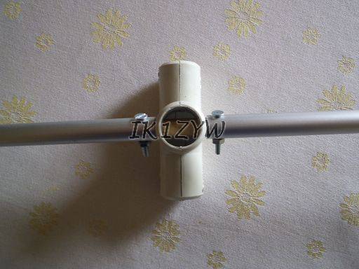
T-shaped connectors were modified as follows:
Inner blocks found inside the upper T part were removed with a file so that the connector would fit tightly the boom
A hole as large as reflector/directors diameter was drilled through the T "leg", taking care to drill orthogonally to the (future) boom direction
Elements were slid through the holes and luckily inherent tolerances provided a good grip between the two. If the element tends to slide it can be held in place with some PVC electric insulation tape (not shown in these pictures).
Boom to mast connection is achieved with another T connector. Since the boom is circular, the operator needs to align elements on the same plane at every installation. An alignment mark can be drawn to speed-up subsequent assemblies. If T connectors become loose, or some wind blows, PVC tape can be used to strengthen the whole setup (not shown in these pictures, but the second director shows signs of previous use of PVC tape).
Pictures show my hybrid version with PVC boom and element mounts, that retained the original with-screws radiator. This arrangment passed the MFJ-259 test, and returned the same impedance values as with metallic boom.
I did a quick comparative measurement between the two versions and noticed no difference in received signal (front lobe, max gain). For the test I assembled both versions and measured the received signal of a weak beacon using Argo software. Strength was measured as the delta between 700Hz beat tone and background noise. Both "ear" and Argo figures suggested me that there is no front gain difference between the two setups.
In the future I might try to figure out modifications in the radiaton pattern, but I first need to find a 360deg open location.
Field trials are next as well as a no-screw version of the radiator (preview in the third picture).
January 2006 UPDATE: I built a no-screw version of the radiator in a standard plastic box that fits the PVC boom through one of those T-connectors!
What "extra" is needed: another drilled T-connector, a plastic box for home electrical wiring with proper pre-cut holes.
I think two pictures can explain better than 1000 words how the radiator is installed into the box, so, here they are:
The hole where the T-connector enters the box is aligned with those used for dipole elements.
Eccetto dove diversamente specificato, i contenuti di questo sito sono rilasciati sotto Licenza Creative Commons.
The material on this page is licensed under a Creative Commons License, unless otherwise noted.
 Right after using with success an homemade reproduction of DK7ZB's VHF 4 element short yagi, I felt the need to make slight changes to accomodate my needs.