Build Them. Enjoy Them!
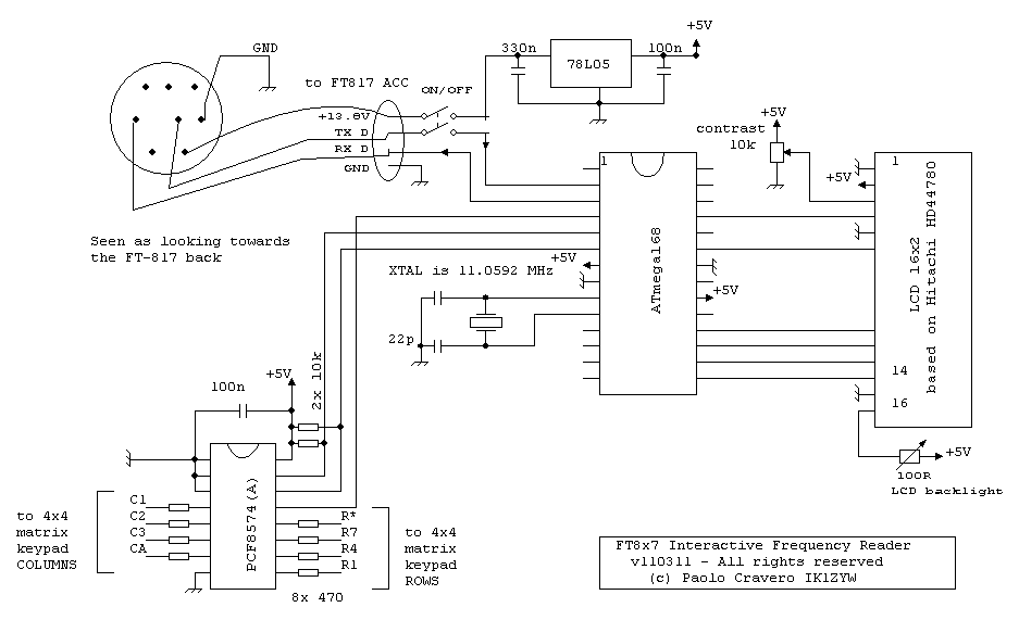
The circuit diagram is stable. The diagram below lacks details on LCD contrast control, for which you should refer to your display datasheet (click to open/download the image):
If you can program the ATmega168 on your own, please refer to the Frequency Reader user's manual for fuse settings (available in the Downloads page). Then write to the microcontroller both the .hex and the .eep files you can download at the same location..
The circuit is very simple and takes power supply from the ACC port of the radio. Labels shown towards FT817 ACC port match those of the radio User's Manual. Six wires to a HD44780 display are shown according to the most popular pin assignment. Keep in mind that the 78L05 100mA limit might be insufficient with LCD backlight ON: check the backlight current draw, keep it at 10mA or use an external voltage source (like a PP3 9V battery).
2010-10-27: WARNING! I have decided to change the display chip from ATtiny2313 to ATmega48/88/168, see the blog post. The circuit described below works 100% as described in the info page, so if it is enough for your needs and you want it now, then go for it. Please email me the request for the firmware .hex file or the programmed chip.
So, you want to give the Frequency Reader a try. If you have already built the External Keypad and made provision for a removable keypad (such as using a row of pin headers) you need to get hold of a HD44780 compatible 2*16 display (about 10€ @2010), "export" +5V and GND from the keypad board and arrange an adapter board. The Display User's Manual (will) show an overlayed circuit diagram keypad//display.
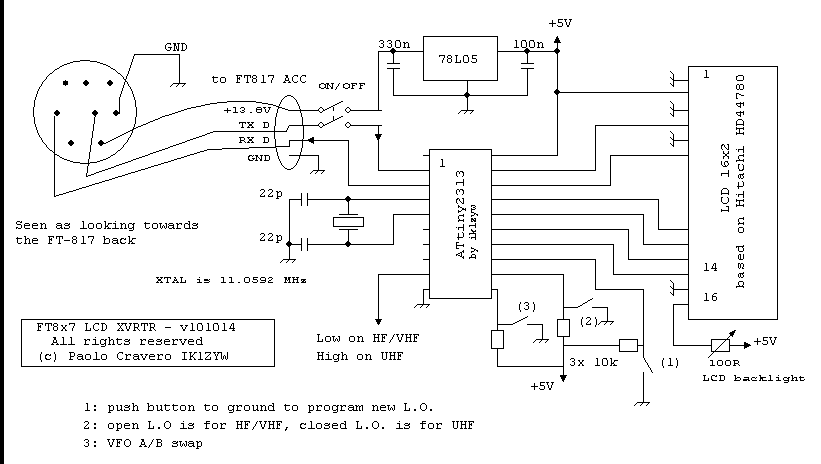
The Frequency Reader circuit is (click to open/download the image):
The circuit diagram shown is for the transverter firmware, but it does work for the "normal" version too.
Parts list is as follows (in red color are shown additional differences with the keypad circuit):
- 1x ATtiny2313-20PU
- 1x 20 pin DIL socket
- 1x 11.0592 MHz XTAL
- 2x 22pF (or 27pF)
- 3x 10kohm 1/4W
- 1x 100ohm trimmer (if LCD has backlight)
- 1x 330nF
- 1x 100nF
- 1x 78L05
- 1x 2x16 HD44780 LCD display
- 1x 1m cable 3 wires + shield
- 1x MiniDin8 plug
- 1x 10x5 cm perfboard or PCB
- 1x DPDT switch (optional)
- 3x N.O. pushbuttons
If you can program the ATtiny2313 on your own, please refer to the keypad User's Manual for fuse settings. Then write to the microcontroller both the .hex and the .eep files you can get on explicit request.
The circuit is very simple and takes power supply from the ACC port of the radio. Labels shown towards FT817 ACC port match those of the radio User's Manual. Six wires to a HD44780 display are shown according to the most popular pin assignment. Keep in mind that the 78L05 100mA limit might be insufficient with LCD backlight ON: check the backlight current draw, or keep it at 10mA.

Eccetto dove diversamente specificato, i contenuti di questo sito sono rilasciati sotto Licenza Creative Commons.
The material on this page is licensed under a Creative Commons License, unless otherwise noted.

