Build Them. Enjoy Them!
 The IK1ZYW keypad is a homebrewer project: you
have to build it (or have someone do it for you). The schematic diagram and
free firmware are available through these pages and in the User's Manual.
In order to build the keypad you will need the following:
- basic soldering skills and tools
- User's Manual and firmware from the Downloads page
- a way to program the firmware on an Atmel ATtiny2313 (read on)
- required components
In case you prefer not to deal with programming the microcontroller or have troubles sourcing all parts see the "Get it" page for further details.
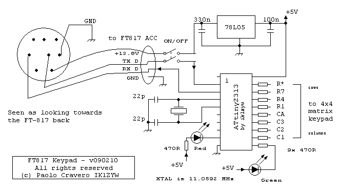
Here you are the schematic diagram (click to open/download the image):
Parts list is as follows:
- 1x ATtiny2313-20PU
- 1x 20 pin DIL socket
- 10x 470 ohm ¼W
- 1x LED red
- 1x LED green (optional)
- 1x 11.0592 MHz XTAL
- 2x 22pF (or 27pF)
- 1x 330nF
- 1x 100nF
- 1x 78L05
- 1x Matrix 4x4 keypad
- 1x 1m cable 3 wires + shield
- 1x MiniDin8 plug
- 1x 10x5 cm perfboard or PCB
- 1x DPDT switch (optional)
You are encouraged to use 8-way pin headers for connecting the matrix keypad to the circuit board.
The circuit is very simple and takes power supply from the ACC port of the radio. Labels shown towards FT817 ACC port match those of the radio User's Manual. Eight wires to a 4x4 matrix keypad are labeled according to the first matching key in the row/column. DO verify with an ohm-meter which lines are connected at each key press. In other words: draw the connection map of your flavour of keypad before connecting it to the chip.
LED and its resistor can be left out. The ON/OFF switch is also optional, but helps to reduce power consumption and/or RX interference (if any): otherwise there is no other way to reset or switch the keypad off than unplug it from the rear of the radio.
Further details on assembly and chip programming are detailed in the User's Manual.

Eccetto dove diversamente specificato, i contenuti di questo sito sono rilasciati sotto Licenza Creative Commons.
The material on this page is licensed under a Creative Commons License, unless otherwise noted.
